For safety,please do follow the instruction strictly to manage this product.
This manual is copyrighted and may not be copied, cut, or modified without permission. Once found, the company will retain the contents of the manual without prior notice
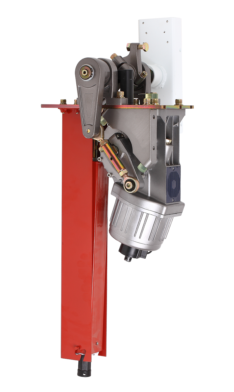
Product Outline
Thanks for you to buy our product.This product uses the new mold designing technology,mold stamping,die casting technology,no clutch designing.And the quality is more reliable.The mechanism uses the gear worm and crank link structures,and the boom move steady,and easy and quick maintenance.
Product Series

Functions and Features
- Open the barrier gate by motor wheel when power off and automatic locking when power on.
- Special spring device:Both the compression spring and tension spring can be used in the machine.Using the compression spring can avoid the accidents caused by the tension spring.
- Three control buttons: for boom rising,falling and pausing.
- Auto-reverse when the boom meets obstruction.
- Infrared photocells connector is available.
- Both internal and external loop detectors are supported.
- Open,Close and Sop controlling interfaces.
- RS-485 communication serial interface(optional)
- Connector for traffic light(AC220V)
- Remote control and wire control for selection
Working environment
- Machine core working temperature: -25℃~+85℃
- Working temperature(control panel): -20℃~+75℃
- Rating voltage:220V±10%,50/60HZ
- Rated Power:100W
- Humidity:≤90%RH
- Distance of remote control:100M>L≥30M in the open place
- Net weight:65kg
Machine Core Components

Installation Direction Definition


Installation and Adjustment
1、Equipment installation
1. Please select the correct type of barrier gate according to the specifications of the pace,and then fix the barrier cabinet with expansion bolts.
After determined the position,the barrier gate foundation should be done according to the site conditions,and also make the cast-in-place basement for the non-concrete ground.

Unlock the clutch device withe the clutch key clockwise.Move the boom to the horizontal and vertical position manually to make sure there is no obstruction.Then turn on the power.

2、Adjustment and Use for the Mechanism Part
The barrier gate has been well set in our factory,but it can be further debugged if there is any problem in usage.
Dismantle the machine coping:
- Remove the fixed screws which were fixed under the boom tray.
- Open the machine door and loose the lock screws.
- Take away the coping.
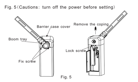
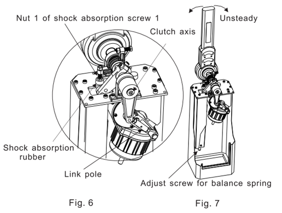
Fig.7(Attention:The clutch device should be locked in these methods.)
- If the boom is not in the vertical position:(refer to fig.6)
- raise up the boom to the vertical position,then loose the Nut 1 of shock absorption screw 1to diminish the press to the shock absorption rubber A.
If there is a gap between the screw A and rubber as the boom is in vertical position,please adjust it again until the press is just right. - Adjust locknuts in both sides of link pole until the boom is vertical.Then tighten up the locknuts again.
- If the boom is unsteady in the horizontal position:(refer to fig.7) screw the adjusting screw of the balance spring clockwise to enhance the spring tension.
(Attention:the spring tension could not be too hard.)
The best methods to adjust the boom(Attention:the clutch device should be unlocked in these methods,)please try as follow:
- Unlock the clutch device and erect the boom manually.
If the boom cannot keep standing or fall down easily,that means the balance spring is not tensional enough.In this case,move the boom to the vertical position and adjust the screw which is used to balance the spring. - Move the boom to 45 degrees manually.
If the boom is still easy to fall down,repeat the step the above step,until the boom does not fall down anymore and has the trend of moving upwards. - Change a new balance spring then readjust the boom again.
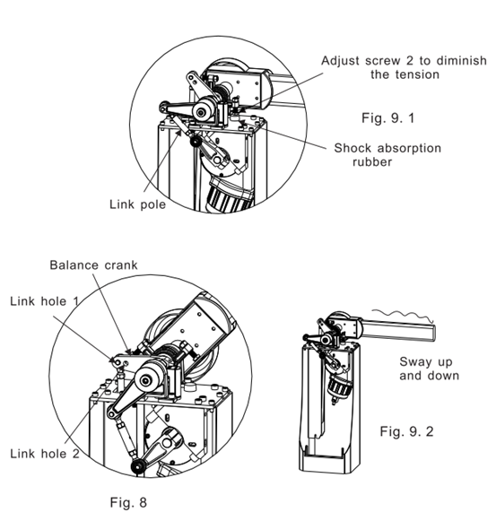
If the boom is vibrant too much when it backtracks in case of coming across any obstacle,please try as follow:(refer to fig.8) - Turn off the power,unlock the clutch device with the clutch key clockwise,and erect the boom to the vertical position manually.Adjust the adjusting screws of the balance spring anticlockwise to diminish the tension of the spring.
- Repeat step(5-a)
- If the balance spring has been adjusted to the tension,the problem still could not be solved.Please hang the balance spring to link pole 2 instead of link pole 1.
If the problem still exists,please change a smaller line diameter spring and repeat the above steps.
Methods to make the boom in the horizontal position:
(Attention:The clutch device should be locked in these methods)
- If the boom is not at the exact horizontal position,please try as follow:
- Refer to Fig.9-1,fall down the arm,and then adjust the shock absorption screw 2 to ,make the boom in the horizontal position.If it doesn’t work,try the next step.
- Loosen the locknuts on both sides of the link hole,rotate the link hole right or left to adjust the arm,then screw down the locknuts again when the boom is in the horizontal position.
- If the boom is vibrant as it falls down to the horizontal position.
- Refer to Fig.9-1,adjust the shock absorption screw B to diminish the press to the shock absorption rubber B(shock absorption cushion):if the adjusting is not satisfied,please try as follow.
- Unlock the clutch device,and rise up the boom to the vertical position manually.Rotate the adjusting screw for balance spring to enhance or diminish the tension.
- Lock up the clutch device and run the machine.If the problem still exists,retry the above steps.
The method to lock up unlock device.The clutch can not be unlocked.Insert the clutch key and rotate it.If the clutch device could not been locked up or unlocked easily,please pull up or pull down the boom by hand lightly(Refer to Fig.4)
3、Spring adjustment
Balance spring
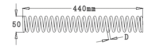
The parameter for selecting the balance tension spring

Inbuilt spring:
Inbuilt spring:line diameter is 3.0mm;
Length is 145mm;
External diameter is 26mm.
The length of the boom from 5.5 to 6 meters has additional instruction for inbuilt spring.
In order to make a safe and steady performance and to decrease the metal fatigue of the balance spring,3 inbuilt springs covered with PVC pipe are inserted into the 6.5mm compressed balance spring and separated with rubber cushion.
Spring installation
- Select a suitable spring together with the screw mandrel and insert them into the spring sleeve.
- Put the whole assembled sleeve into the spring bracket.
- Make the screw mandrel connected to the balance crank by the link hole 1 or link hole 2.
- Install the gasket and the screw at the bottom of the screw thread pole.
- Spin the screw clockwise to adjust the press of the balance spring,so that it can balance the weight of the arm.
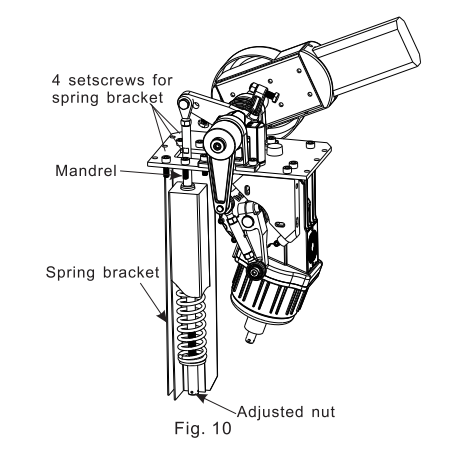
Spring replacement
- Rise up the boom to the vertical position.If the power if off,unlock the clutch device,put the boom to the vertical position manually,and make sure the boom would not fall down.
- Spin the bottom adjusting nut anticlockwise to disassemble it and the baffle ring.
- Loosen 4 setscrews to take off the spring sleeve for changing the new spring(Refer to Fig.10)
- Insert the screw mandrel again and fix it to the selected link hole.
- Rise up the boom to the vertical position again and make sure the boom will not fall down.
- Install the adjusting nuts and the baffle ring in the lower part of the screw mandrel and adjust the press to the balance spring,so that it can balance the weight of the arm.
4、Spring adjustment
The bottom screw can be screwed clockwise or anticlockwise to adjust the press to the balance spring.(Refer to Fig.11)
- In the uptrend area,the boom will move upright because of the balance spring.
- The boom can keep balance and motionless in any position of the balance area.
- In the downtrend area,the boom will fallen down to horizontal position because of the gravity.

5、Installation and Connections of the Electric Part
Electrical Connections
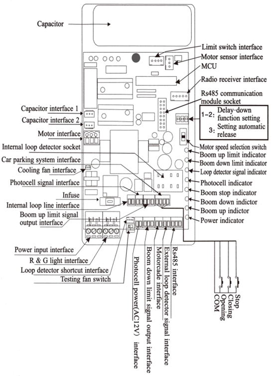
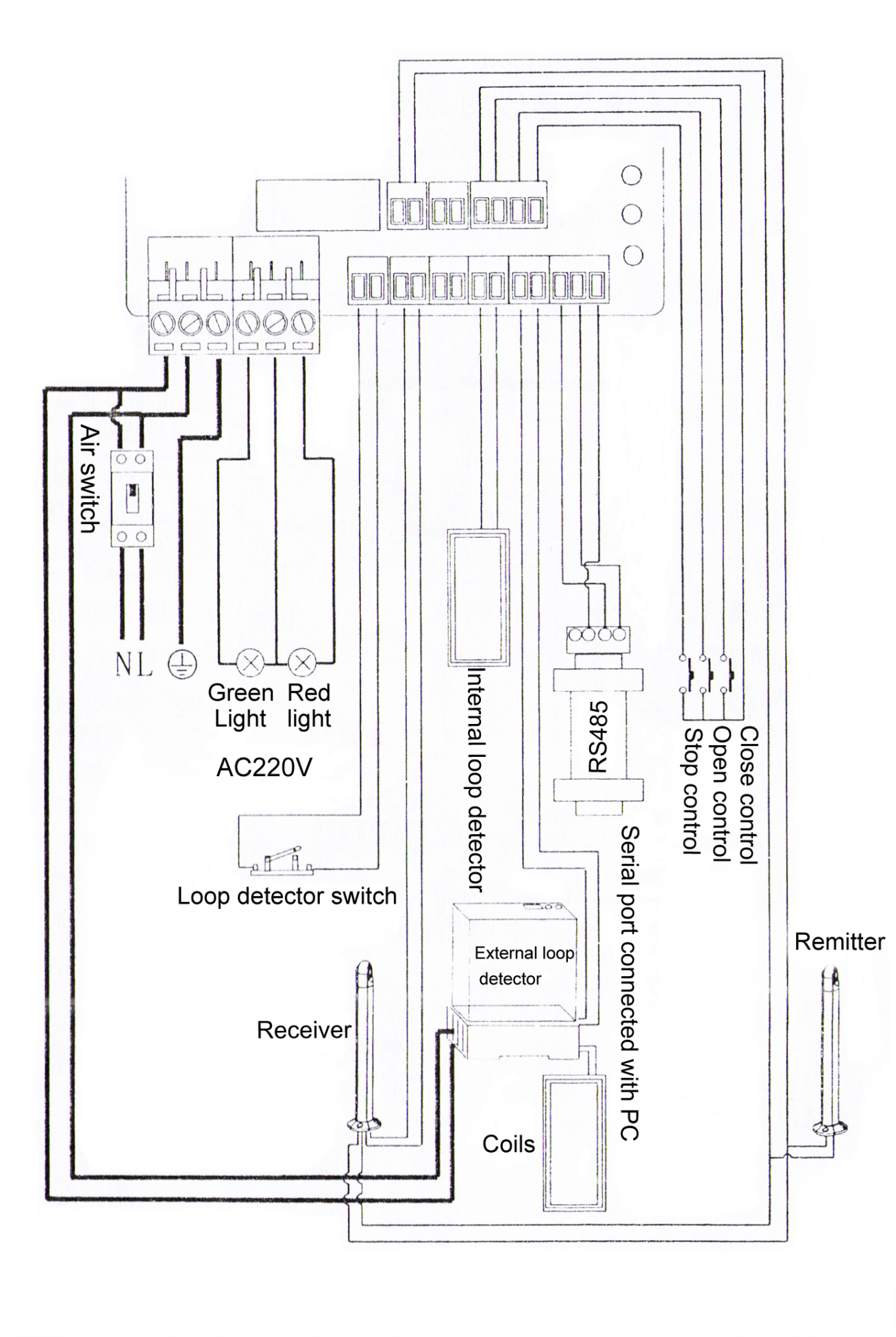
- 220V(110V)power terminal:
Take off the output terminal cover and plugin the power wire. - The traffic light (R&G light) connection:
Traffic light connector is for 220v power.Connect the Red Light Wire to R output terminal,the Green Light Wire to G output terminal.And the COM terminal is the loop input terminal for the traffic light circuit. - Infrared emitter and receiver:
To use this device,first connect the infrared device to power output terminal,and then connect the receiver to the infrared signal input terminal. - Loop detector terminal:
This controller can support both the internal and the external loop detector connections.
However,just one way can be chosen.
If external loop detector is selected,just connect the loop detector to 220V power,and connect the signal wire to the signal input terminal.
If the internal loop detector is selected,connect the internal loop detector to the socket on the circuit board directly and the signal wire to vehicles detector signal input terminal. - “COM”,“UP”,“DOWN”,“STOP”signal input terminal.
The input terminal can work as a switch.If choose the “UP”, “DOWN”, “STOP”input terminal to connect the “COM” by a wire ,the main board will give the correlative reaction signal to the barrier gate arm.
The user can use this method for the IC system controlling or the circuitry controlling.(Note:the wire control is advised to be used in the guards’ room) - “UP ”and “ DOWN” position limit switch.
This switch transmits the “UP” and “DOWN” command to boom by optical signal(Notice:More details please refer to Fig.12) - RS485 serial communication terminal:
The main board supports the RS485 serial communication to control the boom UP and DOWN.Please link the computer with RS485 interface by the communication module.
The software please refer to the instruction in the disk.(Optional device) - Terminal special for motorcade:
If the users have installed the loop detector,and do not want the barrier boom fall down automatically when there are still some cars in line behind the passing car.Then please add an exterior circuit to this device.If the circuit is on,the loop detector will work;if the circuit is off,the loop detector will not work.
6、Electricity Adjustment and Attentions
- Barrier gate controlling:
There are three buttons to control the barrier gate conveniently when the barrier gate sets well.
If the boom can not fall down or rise up to the right position,or rises up automatically after reaching the horizontal position,please check whether the abnormal situation is caused by loop detector or not.
If the abnormal situation mentioned above is not caused by loop detector ,please check the “Gate Type Selection” setting.
(Note: the barrier gate speed has been fixed.And this “Gate Type Selection” is just for controller adjustment to keep its’ working speed accord with the barrier gate speed.) The “Gate Type Selection” has been well set before leaving our factory,but user can adjust it if needed. - Boom backtrack function:
The boom will rise up if it comes across obstacles when falling.And it will stop if it hits something when rising. - Infrared photocell function:
If the infrared signal is cut off when the boom is falling,the boom will rise up automatically. - R&G light terminal:
The light will turn green only when the boom is at the vertical position.Red light is for other positions. - Loop detector terminal:
If the vehicles detector is installed correctly,the boom will automatically rise up when there is some press of the vehicle on the loop,and it will automatically fall after the vehicles leaves the loop.
7、Common Malfunctions and Solutions
- Motor works but there is no reaction on the arm.
Please check whether the clutch device is locked or not. - There is too much vibrant when the boom is rising or falling.
Please check whether the shock absorption rubber is broken or not.If yes,change a new one.
Please check whether the balance spring is overused and distorted.If yes,change a new one;or spin bottom adjust nut. - The boom could not rise up or fall down to the end.
When change a long boom to a short one,please readjust it.
The sensor does not plug well,please check it.
The “Speed adjust switch” is wrong adjust,please readjust it. - The distance of the remote control decreases
Check whether the charge capacity of the remote controller is enough or not. - There is no reaction when pressing the remote controller buttons.
Please check whether the power is supplied to the barrier gate or not.
Please check whether the fuse is burnt out or not.
Please check whether the code both in the remote controller and the control board are accordant or not. - There is no reaction on the motor when user changes a control board.
Please check the capacitance is correctly fixed or not.
Please check the sensor is right inserted or not. - If the user changes a new control board and the boom is abnormal when rising and falling.
Please adjust the “Gate Type Selection”(Refer to the control board)
Service Items
- One year’s free servicing is supplied(not including the arm);
- Lifetime charged servicing is offered;
- Technology servicing is supplied.
The following situations are charged for servicing(or changing): - Broken by the wrong installation.
- Broken by improper voltage.
- The surfaces of the system destroyed by wrong installation or use.
- Broken by natural disaster.
- Overdue.
- Servicing items out of our promises.
The upgrade and improvement of the product won’t be notified if there is any.
The explaining authority of this product instruction and service article belongs to the production factory.
Packing List

Remote Control Code
- Learning type
The remote control using special IC learning code remote controller, 418MHz wireless frequency, strong anti-interference, long remote control distance, that can up to 100meters in good weather, use easily and durable. The receiver of learning code remote control can store 16 different remote control codes, and support unlimited number of same code remote control. The external receiver learned the remote control within 5 seconds when power on,press the open/close key at the same time to complete the learning, and reset to continue learn when not complete. If repeat the learning, open the external receiver shell, there is a white button on circuit board, hold down 15 seconds to delete the remote control code, continue to learn or press the white button to learn. - Fixed type
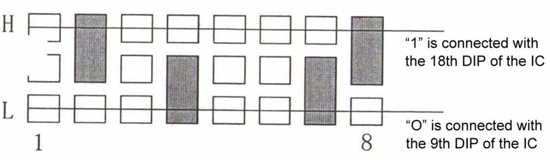
The code of remote controller and remote receiver should be same.IC number for remote controller is 2260 or 2262,for receiver is 2272.Coding method:open the remote controller,take out the battery,there is a dial plate,the direction is from right to left.The solder between middle port and top port is state “0”.The solder between middle port and bottom port is state “1”.Empty is state “X”.The code mark bellow is 01XX1X0X.
Infrared Photocell Installation
