To ensure your safe operation, please strictly in accordance with the provisions of this manual.
This manual is copyrighted and may not be copied, cut, or modified without permission. Once found, the company will retain the contents of the manual without prior notice
Product Outline
The 2nd generation servo gates adopts the international leading technology, mold manufacturing, compact structure, high precision, standardization of consistency. Using planetary reducer transmission, high efficiency, long life, no oil leakage, no blockage and low noise, etc. The motor adopts 24V permanent magnet rare earth synchronous servo motor with the the characteristics of small size, low power consumption, large torque, wide speed regulation, no heat and precise limit, etc., adopt digital signal processor (DSP) as the control core that can realize more complex algorithms, network and intelligent, (IPM) internal integrated drive circuit can detect faults and display faults code that can quickly solve the fault problem. The three-link crank design of the gate can open and close arm more stable. Using solar charging applications, suitable for railway crossings without electricity, fire escapes, gas stations, mine entrances and other unattended occasions, fully realized automatic operation control.
Operation Time and Boom Length Configuration Parameter

Functions
- Open and close speed adjustable
- Arm direction Left and Right can change easily
- When power off, manual open and close arm, and lock itself.
- Wireless remote
- Photocell I0 port output
- Loop detector anti-collision I0 output
- Open and close control input
- 12V traffic light output
- Traffic light signal output
- Open and close limit signal output
- 11.Counting (fleet) input RS485 communication input
- 24V battery input port
- Delay close arm function(1-300 sec. Adjustable)
- Open and close arm speed deceleration function
- One-key setting arm type with corresponding speed
- Arm auto reverse function ( Force adjustable)
- Anti-collision alarm function (additional sensors and alarms are required)
Technical Parameters
200W:
Working Temperature:-35℃~+60℃
Power Supply:24/100/240VAC,50/60Hz
Open/close Speed:0.9Sec-8Sec(Adjustable)
Rated Power:200W
Driving Method:Servo motor
Humidity:≤90%
Remote Control Distance:≤100m(open,sunny weather)
Protection Grade:IP54
Motor No – load Speed:3000r/min
Max Boom Length:3m-6m
400W:
Working Temperature:-35℃~+60℃
Power Supply:24/100/240VAC,50/60Hz
Open/close Speed:0.6Sec-6Sec(Adjustable)
Rated Power:400W
Driving Method:Servo motor
Humidity:≤90%
Remote Control Distance:≤100m(open,sunny weather)
Protection Grade:IP54
Motor No – load Speed:3000r/min
Max Boom Length:2.5m
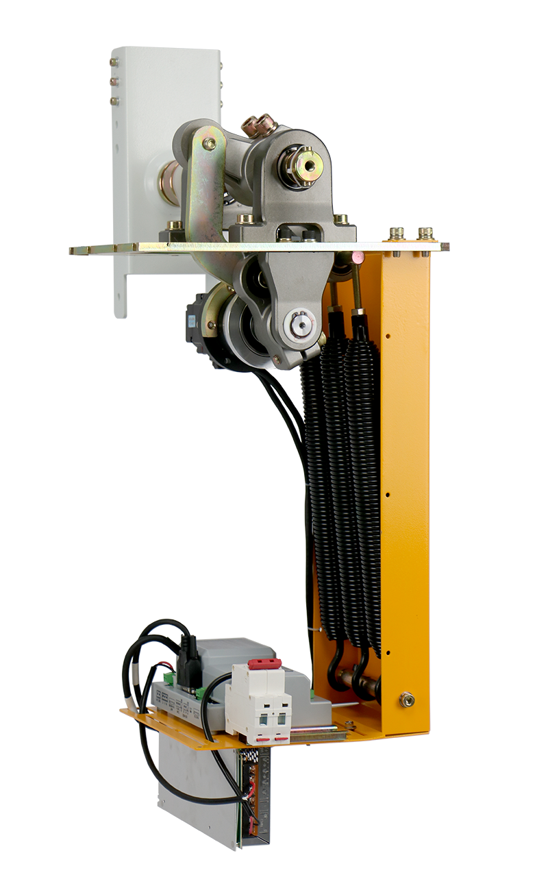
Diagram of 5th DC brushless mechanism

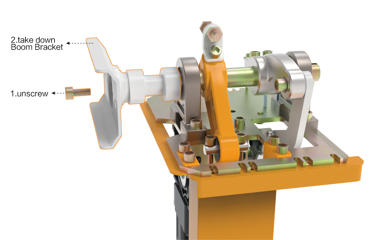
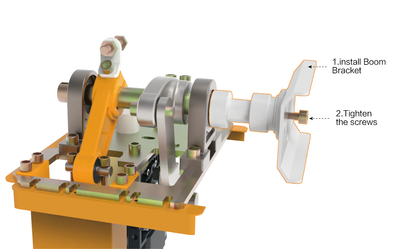
Arm direction change instruction
Servo motor can change arm direction LEFT or RIGHT,6 process.First step:Remove the original left side of the electronic control board bracket and install it to the right; Step 2: Remove the M8X20 hexagon socket screw that fixes the motor and lift out the motor; Step 3: Remove the fixing screw on the boom bracket (see Figure 1 ); Step 4: Use M14X150 screws to pull out the boom bracket (as shown in Figure 2); Step 5: Install the extracted bracket from the original left to the right, or the original right to the left; Step 6: Install back to the case, fix M8X20 hexagon socket screws, and the left and right exchanges are completed, no need to adjust other settings.
Schematic diagram of disassemble of left and right interchange
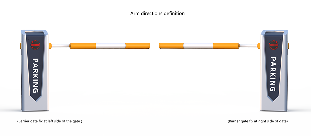
Product Size and Arm directions definition

Installation, commissioning and use
1、Equipment installation
1. Please select the correct type of barrier gate according to the specifications of the pace,and then fix the barrier cabinet with expansion bolts.
After determined the position,the barrier gate foundation should be done according to the site conditions,and also make the cast-in-place basement for the non-concrete ground.

2、Spring selection, installation and adjustment
Barrier gate has been adjusted well before ship out,if there is improper use, it can be further adjusted
Tension spring selection:
Specifications as below:
Diameter 4MM white color
Diameter 4.5MM red color
Diameter 5.5MM blue color
Diameter 6.8MM yellow color
The spring length is subject to the actual product. Design changes will be notified separately.
3、Spring installation,disassemble and replacement
Disassemble step as below: put arm on vertical position:
- Unscrew the M8*140MM screw with a hexagonal spanner
- Calibrate gate arm position
To calibrate the position of the barrier arm (for example, after applying excessive force), follow the steps below:
- Open the door of the barrier box and remove the cover.
- Loosen the two fastening screws of DZ-1 on the pendulum shaft with an M12 Allen key, so that the barrier arm can be repositioned by hand.
- Calibrate the position of the barrier arm (horizontal position, as shown in Figure 1).
- Retighten the two fastening screws with a hex wrench
- Use a wrench to remove an M10 screw on the lower hanging shaft of the spring; if the spring is hooked, you don’t need to take the M10 screw, just take out the spring.

4、Tension spring select table

(the parameter is based on the company’s arm)
5、Installation,dismantlement and adjustment of spring
The steps as follows:
- please keep the boom in the vertical(boom open)position, then tighten 2pcs M12 lock-nut
- According to the balance state of the brake lever, repeatedly adjust the balance spring to adjust the tightness of M8*140mm, and then manually put the brake lever to a 45 degree angle to stop it.
- For the three springs, three springs are required to coordinate adjustments to make the brake lever rise/drop smoothly.
- The swing of the brake lever during lifting and lowering is shown in the figure above. When lifting the lever, the swing of the brake lever is caused by the spring is too tight, and it can be adjusted repeatedly. , Tighten the spring repeatedly.


6、Electrical installation, wiring diagram
- The internal wiring of this machine has been completed when it leaves the factory, please do not change it, just connect the 220V power supply and the protective ground wire to work.
- Traffic light interface: 2A24V voltage traffic light use.
- Infrared anti-smashing interface: external infrared anti-radiation device, and the switch signal of the anti-radiation output can be connected.
- Ground sense interface: support external ground sense. When using an external ground sensor, you only need to connect the switch signal output by the ground sensor.
- Parking system interface wire control interface: connect the switch signal from the system to this interface to control the barrier.
- Starting limit and landing limit signal output: output COM/NO/NC switch signal to the system to inform the current state of the barrier.
- RS485 or CAN communication interface: PC software can be used to manage more than 15 barriers.


7、Function setting description
When setting the function, please press the menu button on the control panel. The Nixie tube displays H00-00 or H00-other numbers. We correspond to the function parameter table code to enter the required function parameter setting. For example, H00-00 is the UP ARM speed adjustment, and then press the confirm button Enter the parameter setting, the number will be displayed on the digital tube, then press the up or down key to set the required UP ARM speed number, and then press the confirm button to complete the ARM-up speed setting.
The other function settings are the same as the example settings.
Servo barrier function setting parameter table

8、Error code

9、Learning type
The company’s remote control adopts IC special learning code remote control, 418MHz wireless frequency, strong anti-interference, long remote control distance, up to 100 meters in fine weather and open places, easy to use and durable. Learning code remote control receiver can store 16 different code remote control codes, the same code remote control unlimited number, the external receiver learns and powers on for 5 seconds while pressing the remote control up and down keys to complete the learning, if no learning is completed, power off and continue learning. If you repeat the learning, disassemble the external receiver shell, there is a white button on the circuit board, press and hold for 15 seconds to delete the remote control code, and then continue to learn, you can also learn on the white button.
Servo arm length and speed comparison table

(the parameter is based on the company’s arm)
Terms of Service
- One-year free maintenance (the brake lever and remote control are not covered by the warranty);
- Provide paid maintenance for life;
- Technical support.
*The following situations are not within the scope of free maintenance (or replacement):
- The user does not install in accordance with the manufacturer’s supporting service manual, causing product damage;
- The use of power is unstable, exceeds the specified use voltage range of the system, and does not meet the national safety power standard, causing product damage;
- The appearance of the system is damaged due to improper installation and use by the user;
- The product is damaged due to irresistible factors such as natural disasters;
- The warranty period has expired;
- Service items promised by non-supporting manufacturers.
Product maintenance and maintenance
- Frequently clean the surface of the cabinet and keep the surface of the barrier clean
- Check whether the fasteners are loose or fall off once a month and fasten them in time
- Check the spring balance after running 30,000 times and reset the balance
- Ask professionals to check the wear of easily worn parts every six months, and replace the worn parts in time
- The remote control distance is too short, please check whether the receiver is shielded by metal objects. Or the battery is low. The remote control distance is greatly affected by the weather. Under severe weather conditions such as rain, fog, wind, and snow, the remote control distance is shortened, which is a normal phenomenon.
Packing List

Appendix
