To ensure your safe operation, please strictly in accordance with the provisions of this manual.
This manual is copyrighted and may not be copied, cut, or modified without permission. Once found, the company will retain the contents of the manual without prior notice
Product Overview
The company produces 1st generation of brushless gates, which adopts international leading technology integrated design and mold manufacturing, compact structure, high precision, high consistency and standardization, and adopts planetary reducer transmission, high efficiency, long life, no oil leakage, no Blockage, low noise and other characteristics. The motor adopts 24V permanent magnet rare earth synchronous servo motor, small size, low power consumption, large torque, wide speed regulation, no heat, small penetration, accurate limit and other characteristics, using digital signal processor (DSP) as the control core that can realize more complex algorithms, realize networking and intelligence, (IPM) internal integrated drive circuit can detect faults and display fault codes to quickly solve fault problems, three-link crank design of the gate, fast open and close operation. Using solar energy charging application that suitable for unattended occasions such as railway crossings without electricity, fire escapes, gas stations, and mine entrances without mains power, and fully realizes automatic operation control.
Type of Arm, Length and Operating Speed Parameters

Functions
- The running speed can be adjusted.
- Arm Can be quickly interchanged.
- Open the arm by motor wheel when power off (no need clutch design), self-locking when up or down.
- Wireless remote control.
- Infrared photocells connector is available.
- Loop detector connector is available.
- Up&Down control input.
- 24V Red&Green light input.
- Red&Green light signal input.
- Up&Down limit signal input.
- Count (motorcade) input RS485 communication input.
- 24V backup battery input
- Delay closing arm function (1-300 sec.)
- Up&Down speed reduction function.
- Arm auto reverse function ( strength can adjust)
- Anti-alarm function ( needs extra sensor and alarm device)
Technical Parameters
Working Temperature:-35℃~+60℃
Power Supply:24/100/240VAC,50/60Hz
Open/close Speed:1.8Sec-6Sec(Adjustable)
Rated Power:200W
Driving Method:DC brushless motor
Humidity:≤90%
Remote Control Distance:≤100m(open,sunny weather)
Protection Grade:IP54
Motor No – load Speed:3000r/min
Max Boom Length:3m-6m
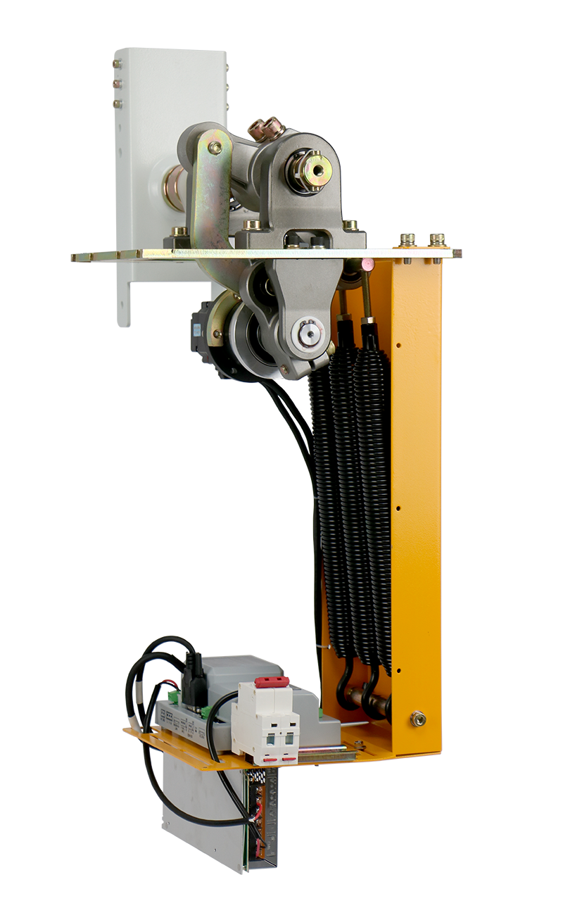
Diagram of 5th DC brushless mechanism

Interchange descriptions
The product direction can be interchanged, divided into 6 steps.
Step 1: remove the M8X20 inner hexagonal screw,take out the machine core;
Step 2: remove the electrical supporting plate from left side to the right side;
Step 3: remove the M1030 fixed screw on the boom tray (see figure 1); Step 4: using the M14150 screw to pull out the boom tray head(see figure 2);
Step 5: install the boom tray head from the original left to the right side,or the original right to the lest side;
Step 6: put the machine core back into machine case, fixed the M8*20 hexagonal screw, direction interchange is completed, no need to adjust other Settings.
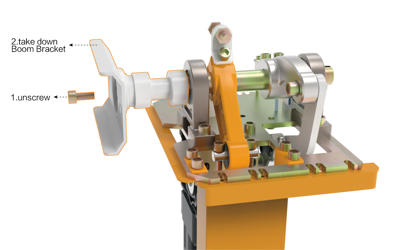
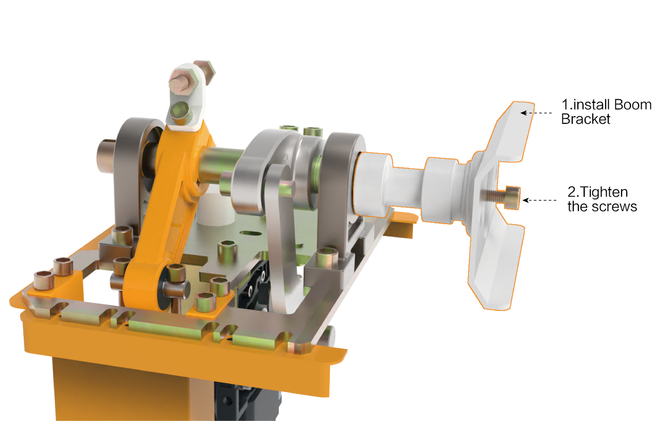
Diagram of disassembly Interchange
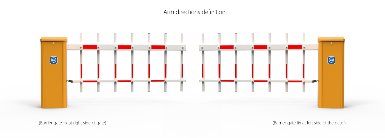
Product Size and Arm directions definition

Installation, commissioning and use
1、Equipment installation
1. Please select the correct type of barrier gate according to the specifications of the pace,and then fix the barrier cabinet with expansion bolts.
After determined the position,the barrier gate foundation should be done according to the site conditions,and also make the cast-in-place basement for the non-concrete ground.

2、Spring selection, installation and adjustment
The barrier gate has been debugged before leaving the factory and can be further adjusted if any needed
Tension spring selection
The spring is stretchable one and the specification is as follows:
Diameter 4.0mm green color
Diameter 4.5mm red color
Diameter 5.5mm blue color
Diameter 6.8mm yellow color
The spring length is subject to the actual product. Design changes will be notified separately.
3、Spring installation,disassemble and replacement
Disassembly steps:put the arm on 90 degree open state:
- Unscrew the M8*140MM screw with a hexagonal spanner
- Calibrate gate arm position
Calibrate the arm position(for example,after using excessive force),follow the below steps:
- open the barrier gate door and remove the cover
- loosen the two fasten screws of the DZ-8 on the boom shaft with the M12’s Allen wrench, so that the boom can be re-positioned by hand.
- adjust the position of the boom (horizontal position, as shown in picture 1).
- Tighten the two fastening screws again by using a hex wrench
- Remove an M10 screw from the lower hanging shaft of the spring with a wretch. If the spring is hooked, you don’t need to remove the screw from the M10, just remove the spring.

4、The parameter for selecting the spring

(the parameter is based on the company’s arm)
5、Balance adjustment of the arm
- First determine the horizontal and vertical state of the arm, and then tighten 2 M12 lock nuts.
- According to the balance state of the arm, repeatedly adjust the balance spring to adjust the tightness of M8*140mm, and then manually place the arm at a 45-degree angle to stop it stably.
- For 3 springs, 3 springs need to be adjusted together, so that the arm can be raised/lowered smoothly.
- The large swing of the arm when the arm UP&DOWN. Adjustment is shown in the figure below. When the arm is lifted, the spring is too tight, and it can be loosened repeatedly; when the arm close with large shaking of the is because the spring is too loose, tight and adjust the spring repeatedly.


6、Electrical installation, wiring diagram
- The internal wiring of this machine has been completed when it leaves the factory. Please do not change it. You only need to connect the 220V power supply and protective ground wire to work.
- Traffic light interface: 2A24V voltage traffic light use.
- Infrared anti-radiation anti-smashing interface: connect an external infrared anti-radiation device, and the switch signal of the radio output can be connected.
- Ground sense interface: support external ground sense. When using an external ground sensor, you only need to connect the switch signal output by the ground sensor.
- Wire-controlled interface of parking lot system interface: connect the switch signal of the system to this interface to control the gate.
- Signal output of starting limit and falling limit: output COM/NO/NC switch signal to the system to inform the current state of the brake.
- RS485 communication interface: PC software can be used to manage more than 16 gates.


7、Function setting description
When setting the function, please press the menu button on the control panel, the nixie tube will display H00-00 or H00-other numbers, we correspond to the function parameter table code to enter the required function parameter setting, for example, H00-00 is the speed adjustment of the starting rod, and then press the confirm button Enter the parameter setting, the number is displayed on the nixie tube, then press the up key or the down key to set the desired number of the starting speed, and then press the confirm key to complete the setting of the starting speed.
Other function settings are for example settings.
Function setting parameter table

8、Error code

9、 Learning type remote control
The remote control using special IC learning code remote controller, 418MHz wireless frequency, strong anti-interference, long remote control distance, that can up to 100meters in good weather, use easily and durable. The receiver of learning code remote control can store 16 different remote control codes, and support unlimited number of same code remote control. The external receiver learned the remote control within 5 seconds when power on,press the open/close key at the same time to complete the learning, and reset to continue learn when not complete. If repeat the learning, open the external receiver shell, there is a white button on circuit board, hold down 15 seconds to delete the remote control code, continue to learn or press the white button to learn.
Arm length speed comparison table

(the parameter is based on the company’s arm)
Service Items
- One year’s free servicing is supplied(not including the arm);
- Lifetime charged servicing is offered;
- Technology servicing is supplied.
The following situations are charged for servicing(or changing):
- Broken by the wrong installation.
- Broken by improper voltage.
- The surfaces of the system destroyed by wrong installation or use.
- Broken by natural disaster.
- Overdue.
- Servicing items out of our promises.
Product Maintenance
- Keep the barrier gate clean
- Check the joints ever month in case of any loose parts.
- Check the spring elasticity after the barrier gate running 3000 times.
- Check the easily worn-out parts(like the spring,limit switch),every half year and renew it.
- Remote control distance will be shortened or not work in case like big object screening,battery exhausting,extreme weathers.
Packing List

Appendix
